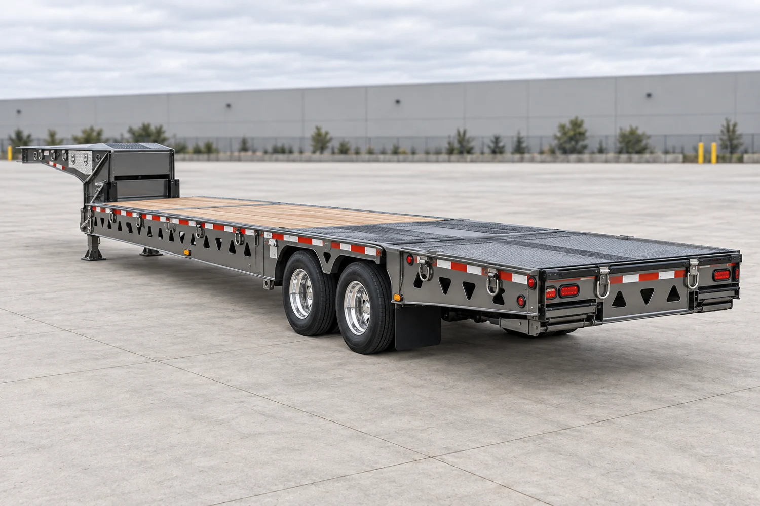
Hydraulic-tail equipment platform · Trail King

TK80HT

Standard two-axle hydraulic tail

Full model specifications →

Hydraulic-tail equipment platform

How this platform works

A hydraulic-tail equipment trailer with an upper-deck ramp and fold-under tail. Transport and loading geometry must be assessed separately.

Separate transport dimensions, main-tail geometry and the tail’s lifting limits.

Loading path

Hydraulic tail

Review the approach onto the main tail and any fold-under section, then the transition onto the deck. Keep the tail’s lifting duty separate from the trailer’s transport rating.

Supporting the load

A wheeled machine can concentrate load during the transition even when its transport weight is below the deck rating. Check support positions through the full loading path.

Dimensions that govern this configuration

Usable support space, nominal deck spans and the overall transport envelope remain separate measurements.

O
Main hydraulic tail length8 ft2,438 mm

Documented spans Shared numeric scale

O Main hydraulic tail length: 8 ft; R Tail fold-under length: 4 ft 4 in; Q Loading ramp length: 10 ft; A Overall transport length: 47 ft 11 inO8 ftR4 ft 4 inQ10 ftA47 ft 11 in

Spans compare documented values. They are not positioned or scaled to the photograph.

Manufacturer stated; loading condition not specified

View dimension source ↗

Documented dimensions

Deck & transport envelope

Overall transport length
47 ft 11 in14,605 mm · Manufacturer stated; loading condition not specifiedSource ↗
Overall / side-rail width
8 ft 6 in2,591 mm · Manufacturer stated; loading condition not specifiedSource ↗
Upper-deck length
9 ft2,743 mm · Manufacturer stated; loading condition not specifiedSource ↗

Height & loading

Main hydraulic tail length
8 ft2,438 mm · Manufacturer stated; loading condition not specifiedSource ↗
Loading ramp length
10 ft3,048 mm · Recessed upper-deck loading ramp; distinct from the rear main tail and not a usable transport deck measurement.Source ↗
Tail fold-under length
4 ft 4 in1,321 mm · Fold-under section of the main hydraulic tail; do not substitute for main-tail length or usable deck length.Source ↗

Coupling & running gear

Coupler height
4 ft 1 in1,245 mm · Manufacturer stated; loading condition not specifiedSource ↗
Kingpin setback
1 ft 2 in356 mm · Manufacturer stated; loading condition not specifiedSource ↗
Swing clearance
7 ft 4 in2,235 mm · Manufacturer stated; loading condition not specifiedSource ↗
Axle spacing
4 ft 1 in1,245 mm · Manufacturer stated; loading condition not specifiedSource ↗

Still needed from the build sheet

  • Main-deck height
  • Main deck / well length (nominal)
  • Usable main deck / well length
  • Usable support width

Ratings & support conditions

concentrated · 10 ft support length50,000 lb22,680 kg

Load supported over 10 ft

Rating source ↗

Tare, gross vehicle rating and structural load ratings describe different limits. None alone establishes allowable payload or legal axle loads.

Plan around the actual load

These applications identify what to investigate. Suitability depends on the transported assembly, support points and the selected trailer build.

Backhoes & telehandlers

What is the final boom and attachment position?

Short wheel contact areas create concentrated deck loading. Record axle reactions where available and keep the load basis explicit.

  • Stowed boom height and rear projection
  • Bucket / fork transport width
  • Wheelbase and tyre contact locations
Paving & road equipment

Will low-clearance components clear the loading path?

A roller drum or milling machine track can concentrate load into a small section. Review flooring and crossmember support as well as total capacity.

  • Screed and conveyor stowed width
  • Lowest frame / drum clearance
  • Track or drum contact pattern
Wheel loaders

Can the tyres and articulation fit the loading path?

Concentrated wheel loads need deck and crossmember verification. Record the actual tyre contact lines rather than treating the whole machine length as load distribution.

  • Outside tyre and bucket widths
  • Wheelbase and axle weights
  • Roof / exhaust transport height

Documented build details

Construction
Steel
Neck
fixed
Running gear
Tandem air ride
Tail approach angle
12.5° manufacturer loading angle; confirm ground and operating setup.Source ↗
Upper-deck ramp
Recessed hydraulic ramp, 11° published loading angle; this is distinct from the main tail.Source ↗
Winch
20,000 lb published winch rating; not the tail lift capacity or a transport rating.Source ↗
Dock position
Tail can reach a published 58 in dock height; an operating position, not loaded deck height.Source ↗

Configuration & inspection

  • Published 52 in fold-under tail; tail raises to a 58 in dock. These are not loaded deck heights.
  • An 8 ft tail and its fold-under section are loading components, not an added continuous main deck.
  • Confirm tail lift capacity and machine breakover before loading.

Equipment selection requires verified weights and ratings, load support, coupling and axle analysis, securement planning and route review. This reference is not engineering, permit or route-clearance approval.