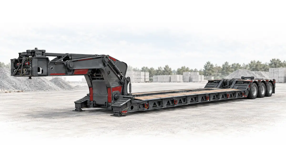
Mechanical detachable lowbed · Trail King

102MG

Current manufacturer reference

Full model specifications →

Mechanical detachable lowbed

How this platform works

A current mechanical detachable gooseneck lowbed with a documented 28 ft 8 in usable deck and 90,000 lb concentrated rating over 16 ft.

The neck arrangement and tractor approach are as important as the well dimensions.

Loading path

Front detach

Use the operating procedure for this mechanical neck. Confirm the tractor approach, roller or ramp arrangement and clearance throughout detachment and reconnection.

Supporting the load

Check the actual support length against the concentrated rating. A similar model name or interchangeable neck does not prove identical ratings.

Dimensions that govern this configuration

Usable support space, nominal deck spans and the overall transport envelope remain separate measurements.

H
Usable main deck / well length28 ft 8 in8,738 mm

Documented spans Shared numeric scale

H Usable main deck / well length: 28 ft 8 inH28 ft 8 in

Spans compare documented values. They are not positioned or scaled to the photograph.

Manufacturer-stated usable deck length

View dimension source ↗

Documented dimensions

Deck & transport envelope

Usable main deck / well length
28 ft 8 in8,738 mm · Manufacturer-stated usable deck lengthSource ↗

Still needed from the build sheet

  • Main deck / well length (nominal)
  • Main-deck height
  • Gooseneck length
  • Kingpin setback
  • Swing clearance
  • Usable support width

Ratings & support conditions

concentrated · 16 ft support length90,000 lb40,823 kg

Load supported over 16 ft

Rating source ↗

Tare, gross vehicle rating and structural load ratings describe different limits. None alone establishes allowable payload or legal axle loads.

Plan around the actual load

These applications identify what to investigate. Suitability depends on the transported assembly, support points and the selected trailer build.

Excavators

Will the stowed machine fit the well?

Track footprint length alone is insufficient. Record where the rollers react into the tracks, and check side rails, outriggers and the position of the machine centre of gravity.

  • Track contact length and shoe width
  • Stowed boom / bucket height
  • Counterweight and attachment weight
Dozers

What travels with the blade and ripper?

Wide tracks need a documented support path. Outrigger boards are not a general-purpose extension of the trailer’s structural rating.

  • Blade width and installed position
  • Ripper projection and ground clearance
  • Track footprint and centre of gravity
Paving & road equipment

Will low-clearance components clear the loading path?

A roller drum or milling machine track can concentrate load into a small section. Review flooring and crossmember support as well as total capacity.

  • Screed and conveyor stowed width
  • Lowest frame / drum clearance
  • Track or drum contact pattern

Documented build details

Construction
Steel
Neck
mechanical detachable
Running gear
Build sheet required
Reinforcement
Manufacturer documents flip-axle reinforcement; installed auxiliary equipment remains build-specific.Source ↗

Configuration & inspection

  • Production start remains unverified.
  • Confirm axle count, stirrup position and installed flip-axle provisions.

Equipment selection requires verified weights and ratings, load support, coupling and axle analysis, securement planning and route review. This reference is not engineering, permit or route-clearance approval.