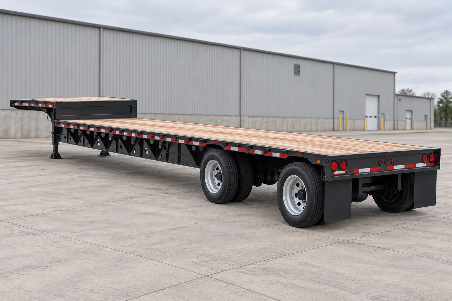
Step deck / single drop · Talbert

Drop Deck

Manufacturer standard reference

Full model specifications →

Step deck / single drop

How this platform works

A fixed-neck steel step deck with separate upper and lower loading areas. The record distinguishes distributed capacity from concentrated support conditions while leaving undocumented deck dimensions unknown.

Treat the upper deck and lower main deck as separate working areas.

Loading path

Winch / crane; verify loading procedure

Side or crane loading needs access to both deck levels. Drive-on loading requires the specified ramps and a checked transition path.

Supporting the load

An overall trailer length includes the upper deck and other structure. Do not subtract one published span to invent a usable lower-deck length.

Dimensions that govern this configuration

Usable support space, nominal deck spans and the overall transport envelope remain separate measurements.

J
Upper-deck length11 ft3,353 mm

Documented spans Shared numeric scale

J Upper-deck length: 11 ft; C Overall / side-rail width: 8 ft 6 inJ11 ftC8 ft 6 in

Spans compare documented values. They are not positioned or scaled to the photograph.

Manufacturer stated; configuration reference

View dimension source ↗

Documented dimensions

Deck & transport envelope

Overall / side-rail width
8 ft 6 in2,591 mm · Manufacturer stated; configuration referenceSource ↗
Upper-deck length
11 ft3,353 mm · Manufacturer stated; configuration referenceSource ↗

Coupling & running gear

Kingpin setback
2 ft 6 in762 mm · Manufacturer stated; configuration referenceSource ↗

Still needed from the build sheet

  • Main deck / well length (nominal)
  • Usable main deck / well length
  • Main-deck height
  • Overall transport length
  • Usable support width

Ratings & support conditions

distributed110,000 lb49,895 kg

Even distribution; verify configuration chart

Rating source ↗
concentrated · 10 ft support length70,000 lb31,751 kg

Stated support length

Rating source ↗

Tare, gross vehicle rating and structural load ratings describe different limits. None alone establishes allowable payload or legal axle loads.

Plan around the actual load

These applications identify what to investigate. Suitability depends on the transported assembly, support points and the selected trailer build.

Generators & industrial skids

Does the skid footprint match the structural support?

Locate the skid rails over suitable structure. Check whether levelling blocks, isolators or delicate equipment prohibit support at other points.

  • Skid contact rails and support spacing
  • Total packaged height with dunnage
  • Lifting-point access and enclosure width
Crane components

Where must the component be supported?

Counterweight stacks create concentrated reactions; lattice boom sections may require separated supports. A distributed deck rating cannot stand in for either case.

  • Component length and maximum section width
  • Approved support and lifting points
  • Component weight and centre of gravity

Documented build details

Construction
Steel
Neck
fixed
Running gear
Exact axle arrangement requires build confirmation
Manufacturer detail
Fixed GooseneckSource ↗
Manufacturer detail
1-1/8 in. Shiplap Apitong FlooringSource ↗
Manufacturer detail
Construction: T1 and 80K BeamsSource ↗
Manufacturer detail
Winch Cable Pipe on Rear of GooseneckSource ↗
Manufacturer detail
35-42 in. Loaded Deck HeightSource ↗
Manufacturer detail
One Pipe Pocket Each End of Rear Gooseneck PipeSource ↗
Manufacturer detail
Cable Roller with Spherical Bearings Between Gooseneck Mainbeams at Rear, Pin Pockets in Front of RollerSource ↗

Configuration & inspection

  • Obtain the actual build sheet and configuration-specific load chart.
  • Published options and family ranges do not establish an individual trailer’s equipment.

Equipment selection requires verified weights and ratings, load support, coupling and axle analysis, securement planning and route review. This reference is not engineering, permit or route-clearance approval.