Traveling-axle equipment platform · Trail King

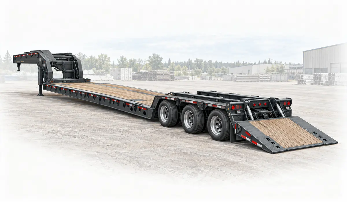
TK110SA

Current manufacturer reference

Full model specifications →

Traveling-axle equipment platform

How this platform works

A current hydraulic sliding-axle platform with a 7-degree loading angle, 110,000 lb uniform rating and 70,000 lb concentrated rating over 10 ft.

Loading position and transport position have different axle and deck geometry.

Loading path

Hydraulic sliding axle / deck-to-ground loading

Review the moving running gear, tilting deck and transition to the upper deck using the operating instructions. Confirm the running gear is in its required transport position.

Supporting the load

Tyre diameter, axle count and suspension settings can change height and load distribution. Retain the exact reference when comparing alternatives.
Dimensions that govern this configuration

Usable support space, nominal deck spans and the overall transport envelope remain separate measurements.

D
Main-deck heightNot documentedConfiguration-specific measurement required

The reference does not establish this measurement.

Documented dimensions

Still needed from the build sheet

  • Main-deck height
  • Overall transport length
  • Main deck / well length (nominal)
  • Upper-deck length
  • Axle spacing
  • Usable support width
  • Usable main deck / well length

Ratings & support conditions

distributed110,000 lb49,895 kg

Uniformly distributed structural rating

Rating source ↗
concentrated · 10 ft support length70,000 lb31,751 kg

Load supported over 10 ft

Rating source ↗

Tare, gross vehicle rating and structural load ratings describe different limits. None alone establishes allowable payload or legal axle loads.

Plan around the actual load

These applications identify what to investigate. Suitability depends on the transported assembly, support points and the selected trailer build.

Wheel loaders

Can the tyres and articulation fit the loading path?

Concentrated wheel loads need deck and crossmember verification. Record the actual tyre contact lines rather than treating the whole machine length as load distribution.

  • Outside tyre and bucket widths
  • Wheelbase and axle weights
  • Roof / exhaust transport height
Backhoes & telehandlers

What is the final boom and attachment position?

Short wheel contact areas create concentrated deck loading. Record axle reactions where available and keep the load basis explicit.

  • Stowed boom height and rear projection
  • Bucket / fork transport width
  • Wheelbase and tyre contact locations
Agricultural machinery

Which parts fold, detach or overhang?

Confirm support locations for implements; a long folded assembly may sit on only a few small feet or wheels.

  • Folded height and secured width
  • Dual-wheel / track support width
  • Header or hitch overhang

Documented build details

Construction
Steel
Neck
fixed
Running gear
Hydraulic sliding running gear; build sheet required
Loading angle
Manufacturer states a 7° loading angle; verify ground conditions and operating setup.Source ↗

Configuration & inspection

  • Production start remains unverified.
  • Confirm installed axle count and transport lock arrangement.

Equipment selection requires verified weights and ratings, load support, coupling and axle analysis, securement planning and route review. This reference is not engineering, permit or route-clearance approval.