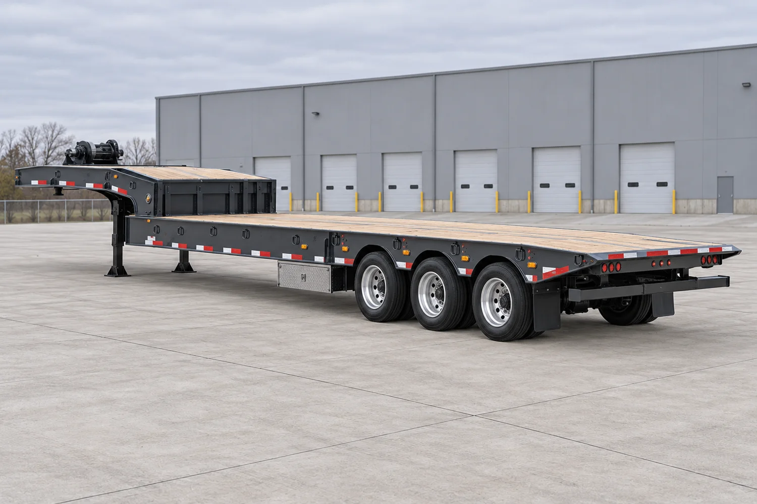
A traveling-axle model with a brochure-documented three-axle configuration. Conflicting product-page and brochure lengths, ratings and swing clearances remain visible and are withheld from automatic comparisons.
Loading position and transport position have different axle and deck geometry.
Loading path
Sliding axle / tilting deck
Review the moving running gear, tilting deck and transition to the upper deck using the operating instructions. Confirm the running gear is in its required transport position.
Supporting the load
Tyre diameter, axle count and suspension settings can change height and load distribution. Retain the exact reference when comparing alternatives.
Dimensions that govern this configuration
Usable support space, nominal deck spans and the overall transport envelope remain separate measurements.
D
Main-deck height3 ft914 mm
Documented spans Shared numeric scale
Spans compare documented values. They are not positioned or scaled to the photograph.
Loaded deck height for TA Series brochure configuration, PUB 230C (0220), page 1. Confirm tyre/suspension/build applicability; not an unloaded height.
8 ft 6 in2,591 mm · Manufacturer stated; configuration referenceSource ↗
Height & loading
Main-deck height
3 ft914 mm · Loaded deck height for TA Series brochure configuration, PUB 230C (0220), page 1. Confirm tyre/suspension/build applicability; not an unloaded height.Source ↗
Still needed from the build sheet
Overall transport length
Main deck / well length (nominal)
Upper-deck length
Axle spacing
Usable support width
Usable main deck / well length
Ratings & support conditions
The exact build’s load chart is required. A model-family capacity range does not establish this configuration’s rating.
Tare, gross vehicle rating and structural load ratings describe different limits. None alone establishes allowable payload or legal axle loads.
Plan around the actual load
These applications identify what to investigate. Suitability depends on the transported assembly, support points and the selected trailer build.
Paving & road equipment
Will low-clearance components clear the loading path?
A roller drum or milling machine track can concentrate load into a small section. Review flooring and crossmember support as well as total capacity.
Can the tyres and articulation fit the loading path?
Concentrated wheel loads need deck and crossmember verification. Record the actual tyre contact lines rather than treating the whole machine length as load distribution.
Large Capacity, Lockable Tool Box on Curb Side with Chain Rack, Updated Hardware and Door SealSource ↗
Manufacturer detail
Two Pair of Pipe Pockets Inside Side Beam FlangeSource ↗
Manufacturer detail
Axle Stops on Last Axle to Prevent Crushing when LoadingSource ↗
Brochure axle configuration
3 axles; model-specific column in TA Series PUB 230C (0220), page 2.Source ↗
Swing clearance source conflict
Source conflict: product page lists 96 in swing radius; linked TA brochure lists 86 in for 5548TA. Swing clearance is withheld pending build-specific confirmation.Source ↗
Configuration & inspection
Source conflict: overview states 48 ft and 110,000 / 80,000 lb ratings; table states 53 ft and 80,000 / 50,000 lb. Lengths and ratings withheld.
Axle count and loaded deck height use the manufacturer-linked TA brochure (PUB 230C, 0220); verify the actual trailer build before relying on them.
Source conflict: product page lists 96 in swing radius; linked TA brochure lists 86 in for 5548TA. Swing clearance is withheld pending build-specific confirmation.
Obtain the actual build sheet and configuration-specific load chart.
Published options and family ranges do not establish an individual trailer’s equipment.
Equipment selection requires verified weights and ratings, load support, coupling and axle analysis, securement planning and route review. This reference is not engineering, permit or route-clearance approval.