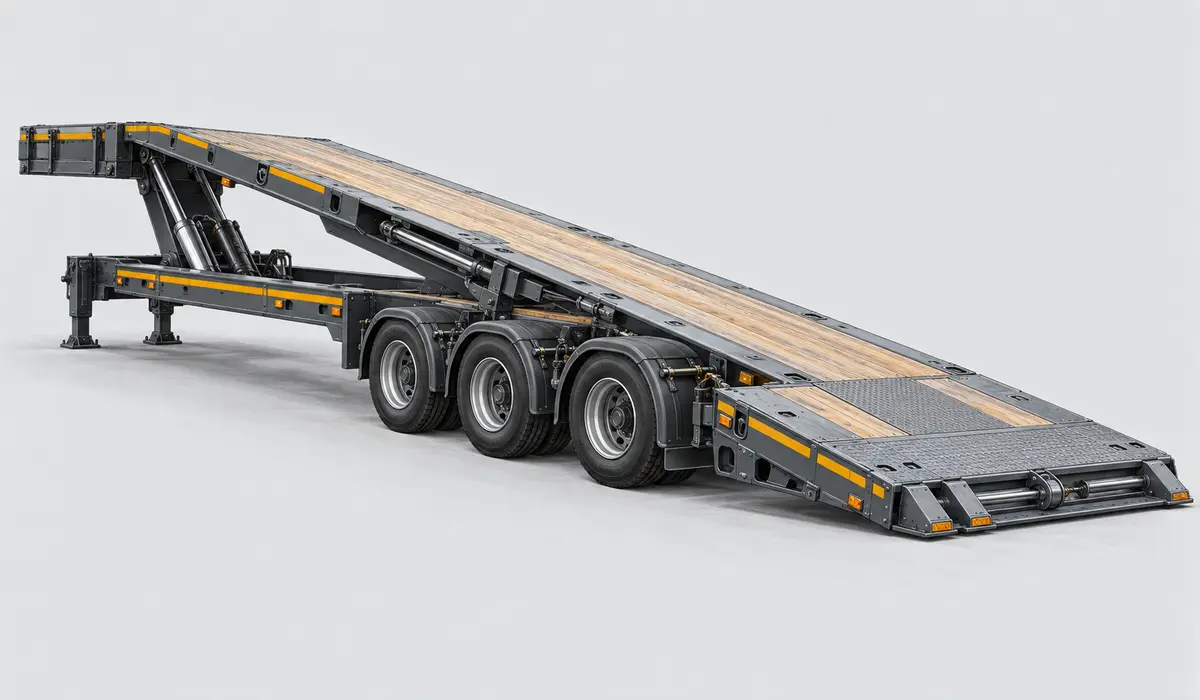
Step deck / single drop · K-Line

45T Tilt Slider

Current manufacturer system reference

Full model specifications →

Step deck / single drop

How this platform works

A named current K-Line 45-ton-class tilt-slider product mechanism using sliding-axle and tilt geometry for ground loading.

Treat the upper deck and lower main deck as separate working areas.

Loading path

Sliding-axle ground loading · Tilt-deck loading

Side or crane loading needs access to both deck levels. Drive-on loading requires the specified ramps and a checked transition path.

Supporting the load

An overall trailer length includes the upper deck and other structure. Do not subtract one published span to invent a usable lower-deck length.

Dimensions that govern this configuration

Usable support space, nominal deck spans and the overall transport envelope remain separate measurements.

B
Main deck / well length (nominal)Not documentedConfiguration-specific measurement required

The reference does not establish this measurement.

Documented dimensions

Still needed from the build sheet

  • Main deck / well length (nominal)
  • Usable main deck / well length
  • Upper-deck length
  • Main-deck height
  • Overall transport length
  • Overall / side-rail width
  • Usable support width

Ratings & support conditions

The exact build’s load chart is required. A model-family capacity range does not establish this configuration’s rating.

Tare, gross vehicle rating and structural load ratings describe different limits. None alone establishes allowable payload or legal axle loads.

Plan around the actual load

These applications identify what to investigate. Suitability depends on the transported assembly, support points and the selected trailer build.

Paving & road equipment

Will low-clearance components clear the loading path?

A roller drum or milling machine track can concentrate load into a small section. Review flooring and crossmember support as well as total capacity.

  • Screed and conveyor stowed width
  • Lowest frame / drum clearance
  • Track or drum contact pattern
Wheel loaders

Can the tyres and articulation fit the loading path?

Concentrated wheel loads need deck and crossmember verification. Record the actual tyre contact lines rather than treating the whole machine length as load distribution.

  • Outside tyre and bucket widths
  • Wheelbase and axle weights
  • Roof / exhaust transport height

Documented build details

Construction
Steel
Neck
fixed
Running gear
Sliding axle / tilt running gear; exact layout requires the build sheet

Configuration & inspection

  • The 45T name does not establish an unqualified payload comparison; exact generations remain unresolved.
  • Obtain the project-specific K-Line engineering package, build sheet and load chart.
  • Gallery capacities, axle layouts and project dates remain configuration evidence, not universal model specifications or production ranges.

Equipment selection requires verified weights and ratings, load support, coupling and axle analysis, securement planning and route review. This reference is not engineering, permit or route-clearance approval.